
Schneider Electric ATV71HU15N4
Altivar 71 drive, 1.5 kW, 480 V, IP20

Read from the product label
- Maker
- Schneider Electric
- Part no.
- ATV71HU15N4
- Serial / rev.
- as printed on your unit
Image is for illustrative purposes only. Please refer to product description.
Delivery options



Schneider Electric ATV71HU15N4 is the IP20 heat sink version of the Altivar 71 drive for 1.5 kW (2 hp) motors at 380 to 480 V, with graphic terminal; the ATV71WU15N4 is the IP54 version.
- Manufacturer
- Schneider Electric
- Manufacturer part no.
- ATV71HU15N4
- Product family
- Altivar 71 Drives (ATV71)
- Type
- AC drive
- Category
- Drives › AC drives (VFDs)
- Lifecycle
- Discontinued
- OEM successor
- Not stated
- Technical datasheet
- Data sheet
Technical specifications
- Manufacturer
- Schneider Electric
- Manufacturer part no.
- ATV71HU15N4
- Type
- AC drive
- Application
- AC drive
- Used with
- Asynchronous motors
- Range of product
- Altivar 71
- Product or component type
- Variable speed drive
- Product specific application
- Complex, high-power machines
- Component name
- ATV71
- Motor power kW
- 1.5 kW, 3 phases at 380...480 V
- Motor power hp
- 2 hp, 3 phases at 380...480 V
- Maximum motor cable length
- 50 m shielded cable; 100 m unshielded cable
- power supply voltage
- 380...480 V - 15...10 %
- Network number of phases
- 3 phases
- Line current
- 5.3 A for 480 V 3 phases 1.5 kW / 2 hp; 5.8 A for 380 V 3 phases 1.5 kW / 2 hp
- EMC filter
- Integrated
- Assembly style
- With heat sink
- Apparent power
- 3.8 kVA at 380 V 3 phases 1.5 kW / 2 hp
- Prospective line Isc
- 5 kA for 3 phases
- Nominal output current
- 3.4 A at 4 kHz 460 V 3 phases 1.5 kW / 2 hp; 4.1 A at 4 kHz 380 V 3 phases 1.5 kW / 2 hp
- Maximum transient current
- 6.2 A for 60 s 3 phases 1.5 kW / 2 hp; 6.8 A for 2 s 3 phases 1.5 kW / 2 hp
- Output frequency
- 0.1…599 Hz
- Nominal switching frequency
- 4 kHz
- Switching frequency
- 1...16 kHz adjustable; 4...16 kHz with derating factor
- Asynchronous motor control profile
- Flux vector control (FVC) with sensor (current vector); Sensorless flux vector control (SFVC) (voltage or current vector); ENA (Energy adaptation) system for unbalanced loads; Voltage/frequency ratio (2 or 5 points)
- Type of polarization
- No impedance for Modbus
- Product destination
- Synchronous motors; Asynchronous motors
- power supply voltage limits
- 323…528 V
- power supply frequency
- 50...60 Hz - 5...5 %
- power supply frequency limits
- 47.5...63 Hz
Show all 95 specificationsShow fewer
- Speed range
- 1…100 for asynchronous motor in open-loop mode, without speed feedback; 1…1000 for asynchronous motor in closed-loop mode with encoder feedback; 1…50 for synchronous motor in open-loop mode, without speed feedback
- Speed accuracy
- +/- 0.01 % of nominal speed in closed-loop mode with encoder feedback 0.2 Tn to Tn; +/- 10 % of nominal slip without speed feedback 0.2 Tn to Tn
- Torque accuracy
- +/- 15 % in open-loop mode, without speed feedback; +/- 5 % in closed-loop mode with encoder feedback
- Transient overtorque
- 170 % of nominal motor torque +/- 10 % for 60 s every 10 minutes; 220 % of nominal motor torque +/- 10 % for 2 s
- Braking torque
- <= 150 % with braking or hoist resistor; 30 % without braking resistor
- Synchronous motor control profile
- Vector control without speed feedback
- Regulation loop
- Adjustable PI regulator
- Motor slip compensation
- Suppressable; Adjustable; Not available in voltage/frequency ratio (2 or 5 points); Automatic whatever the load
- diagnostic
- 1 LED (red) for drive voltage
- Output voltage
- <= power supply voltage
- Insulation
- Electrical between power and control
- type of cable for mounting in an enclosure
- With a NEMA Type1 kit: 3 wire(s)UL 508 cable at 40 °C, copper 75 °C / PVC; With an IP21 or an IP31 kit: 3 wire(s)IEC cable at 40 °C, copper 70 °C / PVC; Without mounting kit: 1 wire(s)IEC cable at 45 °C, copper 70 °C / PVC; Without mounting kit: 1 wire(s)IEC cable at 45 °C, copper 90 °C / XLPE/EPR
- Electrical connection
- Terminal, clamping capacity: 2.5 mm², 14 AWG (AI1-/AI1+, AI2, AO1, R1A, R1B, R1C, R2A, R2B, LI1...LI6, PWR); Terminal, clamping capacity: 4 mm², 10 AWG (L1/R, L2/S, L3/T, U/T1, V/T2, W/T3, PC/-, PO, PA/+, PA, PB)
- Tightening torque
- 0.6 N.m (AI1-/AI1+, AI2, AO1, R1A, R1B, R1C, R2A, R2B, LI1...LI6, PWR); 1.4 N.m, 12.3 lb.in (L1/R, L2/S, L3/T, U/T1, V/T2, W/T3, PC/-, PO, PA/+, PA, PB)
- Supply
- Internal supply for reference potentiometer (1 to 10 kOhm): 10.5 V DC +/- 5 %, <10 mA, protection type: overload and short-circuit protection; Internal supply: 24 V DC (21…27 V), <200 mA, protection type: overload and short-circuit protection
- Analogue input number
- 2
- Analogue input type
- AI1-/Al1+ bipolar differential voltage: +/- 10 V DC 24 V max, resolution 11 bits + sign; AI2 software-configurable current: 0...20 mA, impedance: 242 Ohm, resolution 11 bits; AI2 software-configurable voltage: 0...10 V DC 24 V max, impedance: 30000 Ohm, resolution 11 bits
- input sampling time
- 2 ms +/- 0.5 ms (AI1-/Al1+) - analog input(s); 2 ms +/- 0.5 ms (Al2) - analog input(s); 2 ms +/- 0.5 ms (LI1...LI5) - discrete input(s); 2 ms +/- 0.5 ms (LI6)if configured as logic input - discrete input(s)
- Response time
- <= 100 ms in STO (Safe Torque Off); AO1 2 ms, tolerance +/- 0.5 ms for analog output(s); R1A, R1B, R1C 7 ms, tolerance +/- 0.5 ms for discrete output(s); R2A, R2B 7 ms, tolerance +/- 0.5 ms for discrete output(s)
- absolute accuracy precision
- +/- 0.6 % (AI1-/Al1+) for a temperature variation 60 °C; +/- 0.6 % (AI2) for a temperature variation 60 °C; +/- 1 % (AO1) for a temperature variation 60 °C
- Linearity error
- +/- 0.15 % of maximum value (AI1-/Al1+, AI2); +/- 0.2 % (AO1)
- Analogue output number
- 1
- Analogue output type
- AO1 software-configurable logic output 10 V 20 mA; AO1 software-configurable current 0...20 mA, impedance: 500 Ohm, resolution 10 bits; AO1 software-configurable voltage 0...10 V DC, impedance: 470 Ohm, resolution 10 bits
- Discrete output number
- 2
- Discrete output type
- Configurable relay logic: (R1A, R1B, R1C) NO/NC - 100000 cycles; Configurable relay logic: (R2A, R2B) NO - 100000 cycles
- Minimum switching current
- 3 mA at 24 V DC for configurable relay logic
- Maximum switching current
- R1, R2: 2 A at 250 V AC inductive load, cos phi = 0.4; R1, R2: 2 A at 30 V DC inductive load, cos phi = 0.4; R1, R2: 5 A at 250 V AC resistive load, cos phi = 1; R1, R2: 5 A at 30 V DC resistive load, cos phi = 1
- Discrete input number
- 7
- Discrete input type
- LI1...LI5: programmable 24 V DC with level 1 PLC, impedance: 3500 Ohm; LI6: switch-configurable 24 V DC with level 1 PLC, impedance: 3500 Ohm; LI6: switch-configurable PTC probe 0…6, impedance: 1500 Ohm; PWR: safety input 24 V DC, impedance: 1500 Ohm conforming to ISO 13849-1 level d
- Discrete input logic
- Negative logic (sink) (LI1...LI5), > 16 V (state 0), 11 V (state 1); Negative logic (sink) (LI6)if configured as logic input, > 16 V (state 0), 11 V (state 1)
- Acceleration and deceleration ramps
- S, U or customized; Linear adjustable separately from 0.01 to 9000 s; Automatic adaptation of ramp if braking capacity exceeded, by using resistor
- Braking to standstill
- By DC injection
- Protection type
- Against exceeding limit speed: drive; Against input phase loss: drive; Break on the control circuit: drive; Input phase breaks: drive; Line supply overvoltage: drive; Line supply undervoltage: drive; Overcurrent between output phases and earth: drive; Overheating protection: drive; Overvoltages on the DC bus: drive; Short-circuit between motor phases: drive; Thermal protection: drive; Motor phase break: motor; Power removal: motor; Thermal protection: motor
- Insulation resistance
- > 1 mOhm 500 V DC for 1 minute to earth
- Frequency resolution
- Analog input: 0.024/50 Hz; Display unit: 0.1 Hz
- Communication port protocol
- CANopen; Modbus
- Connector type
- 1 RJ45 (on front face) for Modbus; 1 RJ45 (on terminal) for Modbus; Male SUB-D 9 on RJ45 for CANopen
- Physical interface
- 2-wire RS 485 for Modbus
- Transmission frame
- RTU for Modbus
- Transmission rate
- 4800 bps, 9600 bps, 19200 bps, 38.4 Kbps for Modbus on terminal; 9600 bps, 19200 bps for Modbus on front face; 20 kbps, 50 kbps, 125 kbps, 250 kbps, 500 kbps, 1 Mbps for CANopen
- Data format
- 8 bits, 1 stop, even parity for Modbus on front face; 8 bits, odd even or no configurable parity for Modbus on terminal
- Number of addresses
- 1…127 for CANopen; 1…247 for Modbus
- Method of access
- Slave CANopen
- Marking
- CE
- Operating position
- Vertical +/- 10 degree
- Height
- 230 mm
- Depth
- 175 mm
- Width
- 130 mm
- Net weight
- 3 kg
- Functionality
- Full
- Specific application
- Other applications
- Option card
- Communication card for CC-Link; Controller inside programmable card; Communication card for DeviceNet; Communication card for EtherNet/IP; Communication card for Fipio; I/O extension card; Communication card for Interbus-S; Interface card for encoder; Communication card for Modbus Plus; Communication card for Modbus TCP; Communication card for Modbus/Uni-Telway; Overhead crane card; Communication card for Profibus DP; Communication card for Profibus DP V1
- Noise level
- 43 dB conforming to 86/188/EEC
- Dielectric strength
- 3535 V DC between earth and power terminals; 5092 V DC between control and power terminals
- Electromagnetic compatibility
- 1.2/50 µs - 8/20 µs surge immunity test level 3 conforming to IEC 61000-4-5; Conducted radio-frequency immunity test level 3 conforming to IEC 61000-4-6; Electrical fast transient/burst immunity test level 4 conforming to IEC 61000-4-4; Electrostatic discharge immunity test level 3 conforming to IEC 61000-4-2; Radiated radio-frequency electromagnetic field immunity test level 3 conforming to IEC 61000-4-3; Voltage dips and interruptions immunity test conforming to IEC 61000-4-11
- Standards
- IEC 61800-3 environments 2 category C2; IEC 60721-3-3 class 3S2; IEC 61800-5-1; IEC 60721-3-3 class 3C1; UL Type 1; IEC 61800-3 environments 1 category C2; IEC 61800-3; EN 55011 class A group 1
- Product certifications
- GOST; UL; CSA; NOM 117; C-Tick
- Pollution degree
- 2 conforming to IEC 61800-5-1
- IP degree of protection
- IP20
- Vibration resistance
- 1 gn (f= 13…200 Hz) conforming to IEC 60068-2-6; 1.5 mm peak to peak (f= 3…13 Hz) conforming to IEC 60068-2-6
- Shock resistance
- 15 gn for 11 ms conforming to IEC 60068-2-27
- Relative humidity
- 5…95 % without condensation conforming to IEC 60068-2-3; 5…95 % without dripping water conforming to IEC 60068-2-3
- Ambient air temperature for operation
- -10…50 °C (without derating)
- Ambient air temperature for storage
- -25…70 °C
- Operating altitude
- <= 1000 m without derating; 1000...3000 m with current derating 1 % per 100 m
Technical documents (1)
Key features
- IP20 drive for mounting in a cabinet
- Integrated EMC filter
- 7 logic inputs, 2 analogue inputs, 1 analogue output
- Modbus and CANopen built in
- Option cards for DeviceNet, EtherNet/IP and others
About the Schneider Electric ATV71HU15N4
The Schneider Electric ATV71HU15N4 is the IP20, heat sink version of the Altivar 71 drive; its twin the ATV71WU15N4 is the IP54 version for the same motor. Schneider Electric rates it at 1.5 kW (2 hp) on a 380...480 V three-phase supply, with 4.1 A nominal output current at 380 V. Schneider Electric lists it as discontinued on 1 Jan 2020, with end of service on 31 Mar 2028.
What is the ATV71HU15N4 used for?
The ATV71HU15N4 controls motor speed and torque on demanding machines, mounted in a control cabinet and linked to the machine controller over Modbus or CANopen.
Lifecycle and successor
Discontinued.
Before you order
What to photograph or confirm so the right unit is quoted.
Check the reference ATV71HU15N4 on the drive's rating label, with its product version. Send us a photo of the label and we will confirm the details before quoting.
Other parts in the Schneider Electric Altivar 71 drives family
Listed for reference. They differ from the ATV71HU15N4 in rating, supply, interface or function and are not interchangeable with it unless Schneider Electric says so. Match the part number on your unit.
| Product | Type | Lifecycle | Qty Available | Price | Action |
|---|---|---|---|---|---|
| Schneider Electric ATV71HD18N4Altivar 71 drive, 18.5 kW, 480 V, IP20 | AC drive | Discontinued | On request | On request | View |
| Schneider Electric ATV71WU15N4Altivar 71 drive, 1.5 kW, 480 V, IP54 | AC drive | Discontinued | On request | On request | View |
You may also be interested in
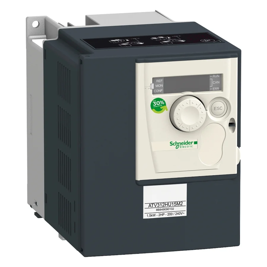
Schneider Electric
Schneider Electric ATV312HU15M2
View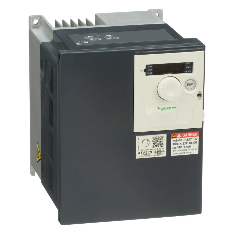
Schneider Electric
Schneider Electric ATV312HU40N4
ViewSchneider Electric
Schneider Electric ATV31C037M2
ViewSchneider Electric
Schneider Electric ATV31HU15M2
ViewSchneider Electric
Schneider Electric ATV61HD18N4
ViewSchneider Electric
Schneider Electric ATV61HU15N4
ViewSchneider Electric
Schneider Electric ATV61WU15N4
View- In stock
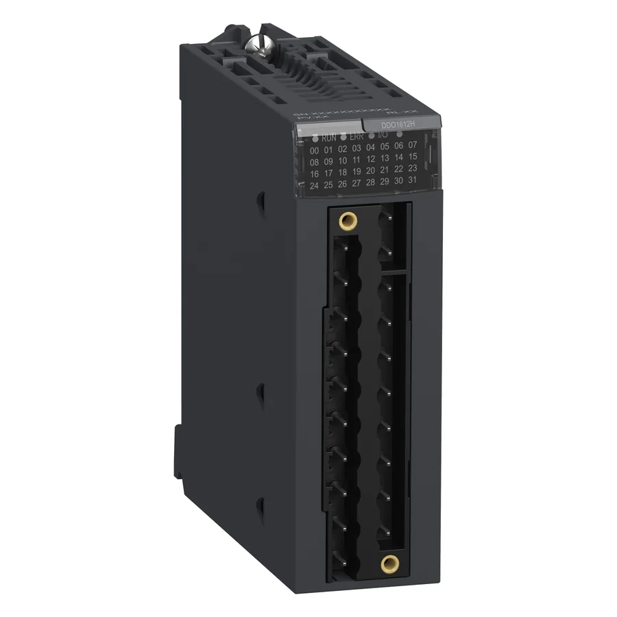
Schneider Electric
Schneider Electric BMXDDO1612H
View 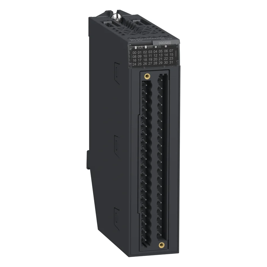
Schneider Electric
Schneider Electric BMXDDO3202
View- In stock
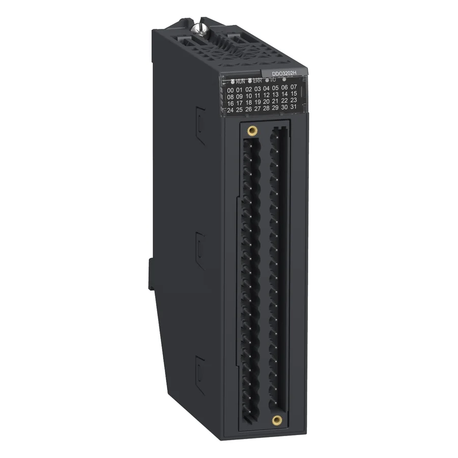
Schneider Electric
Schneider Electric BMXDDO3202H
View 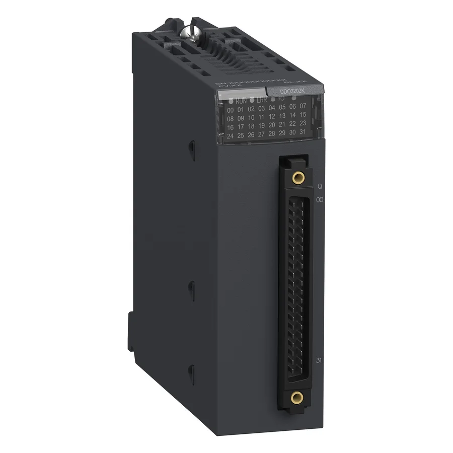
Schneider Electric
Schneider Electric BMXDDO3202K
View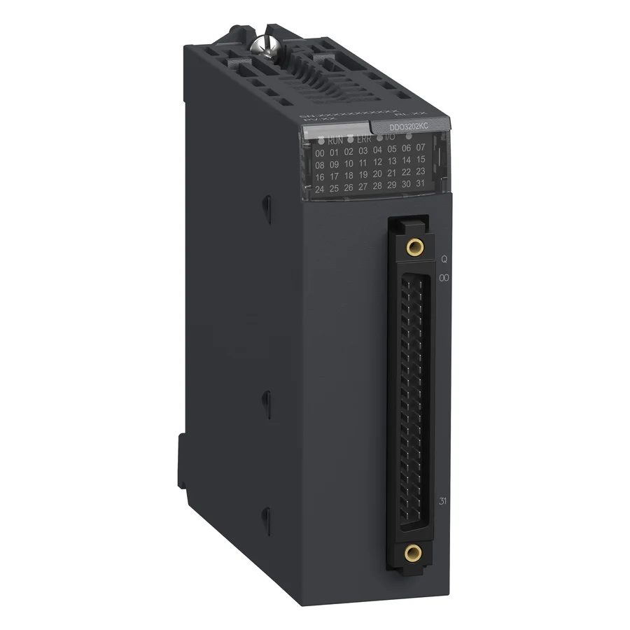
Schneider Electric
Schneider Electric BMXDDO3202KC
View
TimControls is an independent distributor. Manufacturer names and logos are the property of their respective owners and identify products we source; they do not imply manufacturer authorization or affiliation.