

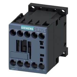
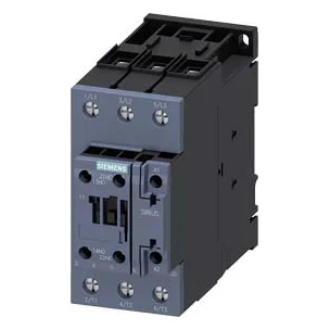
Image is for illustrative purposes only. Please refer to product description.



- Manufacturer
- Siemens
- Manufacturer part number
- 3RT2015-1BB41
- Product family
- SIRIUS 3RT2 Contactors
- Technical datasheet
- Data sheet
Specifications
| Attribute | Value |
|---|---|
| Type | Contactor |
| Manufacturer lifecycle | Active |
| General technical data / size of contactor | S00 |
| product extension / function module for communication | No |
| product extension / auxiliary switch | Yes |
| power loss [W] for rated value of the current / at AC in hot operating state | 0.6 W |
| power loss [W] for rated value of the current / at AC in hot operating state per pole | 0.2 W |
| power loss [W] for rated value of the current / without load current share typical | 4 W |
| General technical data / type of calculation of power loss current-dependent | quadratic |
| insulation voltage / of main circuit with degree of pollution 3 rated value | 690 V |
| insulation voltage / of auxiliary circuit with degree of pollution 3 rated value | 690 V |
| surge voltage resistance / of main circuit rated value | 6 kV |
| surge voltage resistance / of auxiliary circuit rated value | 6 kV |
| General technical data / maximum permissible voltage for protective separation between coil and main contacts according to EN 60947-1 | 400 V |
| shock resistance at rectangular impulse / at DC | 6,7 g / 5 ms, 4,2 g / 10 ms |
Show all 215 specificationsShow fewer specifications
| shock resistance with sine pulse / at DC | 10,5 g / 5 ms, 6,6 g / 10 ms |
|---|---|
| mechanical service life (operating cycles) / of contactor typical | 30 000 000 |
| mechanical service life (operating cycles) / of the contactor with added electronically optimized auxiliary switch block typical | 5 000 000 |
| mechanical service life (operating cycles) / of the contactor with added auxiliary switch block typical | 10 000 000 |
| General technical data / reference code according to IEC 81346-2 | Q |
| General technical data / Substance Prohibitance (day/month/year) | 10/01/2009 |
| General technical data / Net Weight | 277.8 g |
| Ambient conditions / installation altitude at height above sea level maximum | 2 000 m |
| ambient temperature / during operation | -25 ... +60 °C |
| ambient temperature / during storage | -55 ... +80 °C |
| Ambient conditions / relative humidity minimum | 10 % |
| Ambient conditions / relative humidity at 55 °C according to IEC 60068-2-30 maximum | 95 % |
| number of poles for main current circuit | 3 |
| number of NO contacts for main contacts | 3 |
| number of NC contacts for main contacts | 0 |
| operating voltage / at AC-3 rated value maximum | 690 V |
| operating voltage / at AC-3e rated value maximum | 690 V |
| operational current / at AC-1 at 400 V at ambient temperature 40 °C rated value | 18 A |
| operational current / at AC-1 / up to 690 V at ambient temperature 40 °C rated value | 18 A |
| operational current / at AC-1 / up to 690 V at ambient temperature 60 °C rated value | 16 A |
| operational current / at AC-3 / at 400 V rated value | 7 A |
| operational current / at AC-3 / at 500 V rated value | 6 A |
| operational current / at AC-3 / at 690 V rated value | 4.9 A |
| operational current / at AC-3e / at 400 V rated value | 7 A |
| operational current / at AC-3e / at 500 V rated value | 6 A |
| operational current / at AC-3e / at 690 V rated value | 4.9 A |
| operational current / at AC-4 at 400 V rated value | 6.5 A |
| operational current / at AC-5a up to 690 V rated value | 15.8 A |
| operational current / at AC-5b up to 400 V rated value | 5.8 A |
| operational current / at AC-6a / up to 230 V for current peak value n=20 rated value | 4 A |
| operational current / at AC-6a / up to 400 V for current peak value n=20 rated value | 4 A |
| operational current / at AC-6a / up to 500 V for current peak value n=20 rated value | 3.8 A |
| operational current / at AC-6a / up to 690 V for current peak value n=20 rated value | 3.6 A |
| operational current / at AC-6a / up to 230 V for current peak value n=30 rated value | 2.7 A |
| operational current / at AC-6a / up to 400 V for current peak value n=30 rated value | 2.7 A |
| operational current / at AC-6a / up to 500 V for current peak value n=30 rated value | 2.5 A |
| operational current / at AC-6a / up to 690 V for current peak value n=30 rated value | 2.4 A |
| minimum cross-section in main circuit at maximum AC-1 rated value operational current for approx. 200000 operating cycles at | 2.5 mm² |
| AC-4 / at 400 V rated value | 2.6 A |
| AC-4 / at 690 V rated value | 1.8 A |
| operational current / at 1 current path at DC-1 / at 24 V rated value | 15 A |
| operational current / at 1 current path at DC-1 / at 60 V rated value | 15 A |
| operational current / at 1 current path at DC-1 / at 110 V rated value | 1.5 A |
| operational current / at 1 current path at DC-1 / at 220 V rated value | 0.6 A |
| operational current / at 1 current path at DC-1 / at 440 V rated value | 0.42 A |
| operational current / at 1 current path at DC-1 / at 600 V rated value | 0.42 A |
| operational current / with 2 current paths in series at DC-1 / at 24 V rated value | 15 A |
| operational current / with 2 current paths in series at DC-1 / at 60 V rated value | 15 A |
| operational current / with 2 current paths in series at DC-1 / at 110 V rated value | 8.4 A |
| operational current / with 2 current paths in series at DC-1 / at 220 V rated value | 1.2 A |
| operational current / with 2 current paths in series at DC-1 / at 440 V rated value | 0.6 A |
| operational current / with 2 current paths in series at DC-1 / at 600 V rated value | 0.5 A |
| operational current / with 3 current paths in series at DC-1 / at 24 V rated value | 15 A |
| operational current / with 3 current paths in series at DC-1 / at 60 V rated value | 15 A |
| operational current / with 3 current paths in series at DC-1 / at 110 V rated value | 15 A |
| operational current / with 3 current paths in series at DC-1 / at 220 V rated value | 15 A |
| operational current / with 3 current paths in series at DC-1 / at 440 V rated value | 0.9 A |
| operational current / with 3 current paths in series at DC-1 / at 600 V rated value | 0.7 A |
| operational current / at 1 current path at DC-3 at DC-5 / at 24 V rated value | 15 A |
| operational current / at 1 current path at DC-3 at DC-5 / at 60 V rated value | 0.35 A |
| operational current / with 2 current paths in series at DC-3 at DC-5 / at 24 V rated value | 15 A |
| operational current / with 2 current paths in series at DC-3 at DC-5 / at 60 V rated value | 3.5 A |
| operational current / with 2 current paths in series at DC-3 at DC-5 / at 110 V rated value | 0.25 A |
| operational current / with 3 current paths in series at DC-3 at DC-5 / at 24 V rated value | 15 A |
| operational current / with 3 current paths in series at DC-3 at DC-5 / at 60 V rated value | 15 A |
| operational current / with 3 current paths in series at DC-3 at DC-5 / at 110 V rated value | 15 A |
| operational current / with 3 current paths in series at DC-3 at DC-5 / at 220 V rated value | 1.2 A |
| operational current / with 3 current paths in series at DC-3 at DC-5 / at 440 V rated value | 0.14 A |
| operational current / with 3 current paths in series at DC-3 at DC-5 / at 600 V rated value | 0.14 A |
| operating power / at AC-3 / at 230 V rated value | 1.5 kW |
| operating power / at AC-3 / at 400 V rated value | 3 kW |
| operating power / at AC-3 / at 500 V rated value | 3 kW |
| operating power / at AC-3 / at 690 V rated value | 4 kW |
| operating power / at AC-3e / at 230 V rated value | 1.5 kW |
| operating power / at AC-3e / at 400 V rated value | 3 kW |
| operating power / at AC-3e / at 500 V rated value | 3 kW |
| operating power / at AC-3e / at 690 V rated value | 4 kW |
| 4 / at 400 V rated value | 1.15 kW |
| 4 / at 690 V rated value | 1.15 kW |
| operating apparent power at AC-6a / up to 230 V for current peak value n=20 rated value | 1.5 kVA |
| operating apparent power at AC-6a / up to 400 V for current peak value n=20 rated value | 2.7 kVA |
| operating apparent power at AC-6a / up to 500 V for current peak value n=20 rated value | 3.3 kVA |
| operating apparent power at AC-6a / up to 690 V for current peak value n=20 rated value | 4.3 kVA |
| operating apparent power at AC-6a / up to 230 V for current peak value n=30 rated value | 1 kVA |
| operating apparent power at AC-6a / up to 400 V for current peak value n=30 rated value | 1.8 kVA |
| operating apparent power at AC-6a / up to 500 V for current peak value n=30 rated value | 2.2 kVA |
| operating apparent power at AC-6a / up to 690 V for current peak value n=30 rated value | 2.9 kVA |
| 40 °C / limited to 1 s switching at zero current maximum | 120 A; Use minimum cross-section acc. to AC-1 rated value |
| 40 °C / limited to 5 s switching at zero current maximum | 86 A; Use minimum cross-section acc. to AC-1 rated value |
| 40 °C / limited to 10 s switching at zero current maximum | 67 A; Use minimum cross-section acc. to AC-1 rated value |
| 40 °C / limited to 30 s switching at zero current maximum | 52 A; Use minimum cross-section acc. to AC-1 rated value |
| 40 °C / limited to 60 s switching at zero current maximum | 43 A; Use minimum cross-section acc. to AC-1 rated value |
| no-load switching frequency / at DC | 10 000 1/h |
| operating frequency / at AC-1 maximum | 1 000 1/h |
| operating frequency / at AC-2 maximum | 750 1/h |
| operating frequency / at AC-3 maximum | 750 1/h |
| operating frequency / at AC-3e / maximum | 750 1/h |
| operating frequency / at AC-4 maximum | 250 1/h |
| type of voltage of the control supply voltage | DC |
| control supply voltage at DC rated value operating range factor control supply voltage rated value of | 24 V |
| magnet coil at DC / initial value | 0.8 |
| magnet coil at DC / full-scale value | 1.1 |
| Control circuit/ Control / closing power of magnet coil at DC | 4 W |
| Control circuit/ Control / holding power of magnet coil at DC | 4 W |
| closing delay / at DC | 30 ... 100 ms |
| opening delay / at DC | 7 ... 13 ms |
| Control circuit/ Control / arcing time | 10 ... 15 ms |
| control version of the switch operating mechanism | Standard A1 - A2 |
| number of NC contacts for auxiliary contacts instantaneous contact | 0 |
| number of NO contacts for auxiliary contacts instantaneous contact | 1 |
| Auxiliary circuit / operational current at AC-12 maximum | 10 A |
| operational current at AC-15 / at 230 V rated value | 10 A |
| operational current at AC-15 / at 400 V rated value | 3 A |
| operational current at AC-15 / at 500 V rated value | 2 A |
| operational current at AC-15 / at 690 V rated value | 1 A |
| operational current at DC-12 / at 24 V rated value | 10 A |
| operational current at DC-12 / at 48 V rated value | 6 A |
| operational current at DC-12 / at 60 V rated value | 6 A |
| operational current at DC-12 / at 110 V rated value | 3 A |
| operational current at DC-12 / at 125 V rated value | 2 A |
| operational current at DC-12 / at 220 V rated value | 1 A |
| operational current at DC-12 / at 600 V rated value | 0.15 A |
| operational current at DC-13 / at 24 V rated value | 10 A |
| operational current at DC-13 / at 48 V rated value | 2 A |
| operational current at DC-13 / at 60 V rated value | 2 A |
| operational current at DC-13 / at 110 V rated value | 1 A |
| operational current at DC-13 / at 125 V rated value | 0.9 A |
| operational current at DC-13 / at 220 V rated value | 0.3 A |
| operational current at DC-13 / at 600 V rated value | 0.1 A |
| contact reliability of auxiliary contacts | 1 faulty switching per 100 million (17 V, 1 mA) |
| full-load current (FLA) for 3-phase AC motor / at 480 V rated value | 4.8 A |
| full-load current (FLA) for 3-phase AC motor / at 600 V rated value | 6.1 A |
| yielded mechanical performance [hp] / for single-phase AC motor / at 110/120 V rated value | 0.25 hp |
| yielded mechanical performance [hp] / for single-phase AC motor / at 230 V rated value | 0.75 hp |
| yielded mechanical performance [hp] / for 3-phase AC motor / at 200/208 V rated value | 1.5 hp |
| yielded mechanical performance [hp] / for 3-phase AC motor / at 220/230 V rated value | 2 hp |
| yielded mechanical performance [hp] / for 3-phase AC motor / at 460/480 V rated value | 3 hp |
| yielded mechanical performance [hp] / for 3-phase AC motor / at 575/600 V rated value | 5 hp |
| UL/CSA ratings / contact rating of auxiliary contacts according to UL | A600 / Q600 |
| design of the miniature circuit breaker for short-circuit protection of the auxiliary circuit up to 230 V | C characteristic: 10 A; 0.4 kA |
| design of the fuse link / for short-circuit protection of the main circuit / with type of coordination 1 required | gG: 35 A (690 V,100 kA), aM: 20 A (690 V,100 kA), BS88: 35 A (415 V,80 kA) |
| design of the fuse link / for short-circuit protection of the main circuit / with type of coordination 2 required | gG: 20 A (690 V, 100 kA), aM: 16 A (690 V, 100 kA), BS88: 20 A (415 V, 80 kA) |
| design of the fuse link / for short-circuit protection of the auxiliary switch required | gG: 10 A (500 V, 1 kA) |
| Installation/ mounting/ dimensions / mounting position | +/-180° rotation possible on vertical mounting surface; can be tilted forward and backward by +/- 22.5° on vertical mounting surface |
| Installation/ mounting/ dimensions / fastening method side-by-side mounting | Yes |
| Installation/ mounting/ dimensions / fastening method | screw and snap-on mounting onto 35 mm DIN rail according to DIN EN 60715 |
| Installation/ mounting/ dimensions / height | 58 mm |
| Installation/ mounting/ dimensions / width | 45 mm |
| Installation/ mounting/ dimensions / depth | 73 mm |
| required spacing / with side-by-side mounting / forwards | 10 mm |
| required spacing / with side-by-side mounting / upwards | 10 mm |
| required spacing / with side-by-side mounting / downwards | 10 mm |
| required spacing / with side-by-side mounting / at the side | 0 mm |
| required spacing / for grounded parts / forwards | 10 mm |
| required spacing / for grounded parts / upwards | 10 mm |
| required spacing / for grounded parts / at the side | 6 mm |
| required spacing / for grounded parts / downwards | 10 mm |
| required spacing / for live parts / forwards | 10 mm |
| required spacing / for live parts / upwards | 10 mm |
| required spacing / for live parts / downwards | 10 mm |
| required spacing / for live parts / at the side | 6 mm |
| type of electrical connection / for main current circuit | screw-type terminals |
| type of electrical connection / for auxiliary and control circuit | screw-type terminals |
| type of electrical connection / at contactor for auxiliary contacts | Screw-type terminals |
| type of electrical connection / of magnet coil | screw terminal |
| type of connectable conductor cross-sections / for main contacts / solid | 2x (0.5 ... 1.5 mm²), 2x (0.75 ... 2.5 mm²), 2x 4 mm² |
| type of connectable conductor cross-sections / for main contacts / solid or stranded | 2x (0,5 ... 1,5 mm²), 2x (0,75 ... 2,5 mm²), 2x 4 mm² |
| type of connectable conductor cross-sections / for main contacts / finely stranded with core end processing | 2x (0.5 ... 1.5 mm²), 2x (0.75 ... 2.5 mm²) |
| type of connectable conductor cross-sections / for AWG cables for main contacts | 2x (20 ... 16), 2x (18 ... 14), 2x 12 |
| connectable conductor cross-section for main contacts / solid | 0.5 ... 4 mm² |
| connectable conductor cross-section for main contacts / stranded | 0.5 ... 4 mm² |
| connectable conductor cross-section for main contacts / finely stranded with core end processing | 0.5 ... 2.5 mm² |
| connectable conductor cross-section for auxiliary contacts / solid or stranded | 0.5 ... 4 mm² |
| connectable conductor cross-section for auxiliary contacts / finely stranded with core end processing | 0.5 ... 2.5 mm² |
| type of connectable conductor cross-sections / for auxiliary contacts / solid or stranded | 2x (0.5 ... 1.5 mm²), 2x (0.75 ... 2.5 mm²), 2x 4 mm² |
| type of connectable conductor cross-sections / for auxiliary contacts / finely stranded with core end processing | 2x (0.5 ... 1.5 mm²), 2x (0.75 ... 2.5 mm²) |
| type of connectable conductor cross-sections / for AWG cables for auxiliary contacts | 2x (20 ... 16), 2x (18 ... 14), 2x 12 |
| Connections/ Terminals / AWG number as coded connectable conductor cross section for main contacts | 20 ... 12 |
| Connections/ Terminals / AWG number as coded connectable conductor cross section for auxiliary contacts | 20 ... 12 |
| product function / mirror contact according to IEC 60947-4-1 | Yes; with 3RH29 |
| product function / positively driven operation according to IEC 60947-5-1 | No |
| product function / suitable for safety function | Yes |
| suitability for use safety-related switching OFF | Yes |
| Safety related data / service life maximum | 20 a |
| Safety related data / test wear-related service life necessary | Yes |
| proportion of dangerous failures / with low demand rate according to SN 31920 | 40 % |
| proportion of dangerous failures / with high demand rate according to SN 31920 | 73 % |
| Safety related data / B10 value with high demand rate according to SN 31920 | 1 000 000 |
| Safety related data / failure rate [FIT] with low demand rate according to SN 31920 ISO 13849 | 100 FIT |
| Safety related data / device type according to ISO 13849-1 | 3 |
| Safety related data / overdimensioning according to ISO 13849-2 necessary IEC 61508 | Yes |
| safety device type according to IEC 61508-2 Electrical Safety | Type A |
| Safety related data / protection class IP on the front according to IEC 60529 | IP20 |
| Safety related data / touch protection on the front according to IEC 60529 | finger-safe, for vertical contact from the front |
| Environmental Product Declaration / global warming potential [CO2 eq] / during manufacturing | 1.42 kg |
| Environmental Product Declaration / global warming potential [CO2 eq] / during operation | 152 kg |
| Environmental Product Declaration / global warming potential [CO2 eq] / after end of life | -0.305 kg |
| Environmental Product Declaration / global warming potential [CO2 eq] / total | 153 kg |
| Approvals Certificates / General Product Approval Test Certificates | EMV Test Certificates Miscellaneous |
| Maritime application / Miscellaneous | Confirmation Miscellaneous |
Description
The Siemens 3RT2015-1BB41 is a size S00 SIRIUS power contactor. Siemens's data sheet gives a rated operational current of 7 A at AC-3, 3 kW at 400 V, three main contacts, a 24 V DC coil, one NO auxiliary contact and screw terminals. SiePortal lists it as an active product.
Application: Motor contactor
Used with: SIRIUS 3RV2 motor starter combinations, size S00
What is the 3RT2015-1BB41 used for?
It switches small motors, around 3 kW at 400 V, from a PLC output or a control circuit, usually in a starter with a 3RV2 circuit breaker.
Key features
- Size S00, 3-pole
- AC-3 7 A, 3 kW at 400 V
- 24 V DC coil
- Auxiliary contact 1 NO
- Screw terminals
- Mechanical life 30 million operating cycles
Documents and Resources
Associated Products
| Image | Product | Description | Stock | View | Add to RFQ |
|---|---|---|---|---|---|
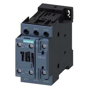 | 3RT2026-1BB40Siemens | Contactor S0, 25 A, 11 kW / 400 V, 24 V DC coil, 1 NO + 1 NC | In stock | View | |
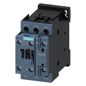 | 3RT2026-1AK60Siemens | Contactor S0, 25 A, 11 kW / 400 V, 110 V AC coil, 1 NO + 1 NC | In stock | View | |
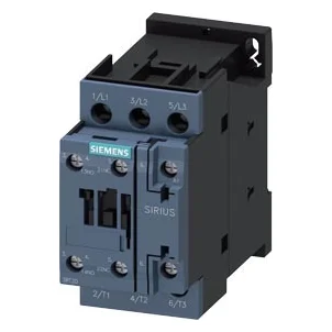 | 3RT2027-1AK60Siemens | Contactor S0, 32 A, 15 kW / 400 V, 110 V AC coil, 1 NO + 1 NC | In stock | View | |
 | 3RT2036-1AK60Siemens | Contactor S2, 51 A, 22 kW / 400 V, 110 V AC coil, 1 NO + 1 NC | In stock | View |
Product Questions
Is the 3RT2015-1BB41 discontinued?
No. Its manufacturer lifecycle status is Active.
Can another Siemens SIRIUS 3RT2 contactors part replace it?
Potential replacements must be checked against the required ratings, dimensions and connections. Sharing a family name does not establish interchangeability.
Do you ship worldwide?
Yes. TimControls ships worldwide. Parts usually ship within 3 to 7 working days of order confirmation, and the exact lead time and shipping options are stated on your quote. Include your delivery country and postal code when you ask for a quote.
Latest news
TimControls is an independent distributor. Manufacturer names and logos are the property of their respective owners and identify products we source; they do not imply manufacturer authorization or affiliation.